11.7.1. Setting up the design task
We are going to start by copying the “nominal” task. Select it, right click it, and choose Copy from the context menu.

Copying the “nominal” design task.
Now, right-click the empty space in the Design tasks tree display and select Paste from the context menu. A copy of the “nominal” design task is created. Right-click it, select Rename from the context menu and enter “corners”. Now you have a new task named “corners” that is a copy of the “nominal” task.
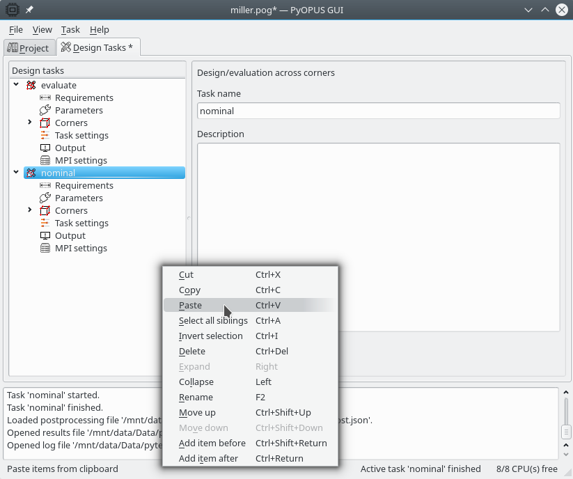
Pasting a copy of the “nominal” design task.
All we need to do is add the corners across which we want the circuit to satisfy all design requirements. One corner is allready present (“nominal”). We will add 16 more corners. These cornerswill represent all combinations of 4 extreme MOS models (wp, ws, wo, and wz), 2 extreme temperatures, and 2 extreme supply voltages. Open the Corners item, select it, and start the corner generator wizard.
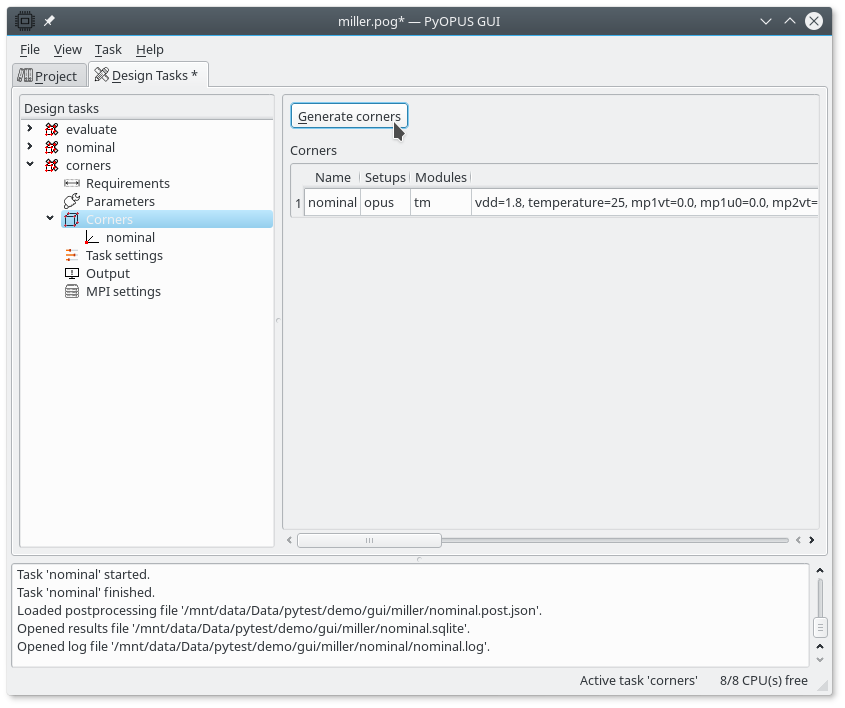
Starting the corner generator wizard.
In the first step we must choose the simulator setups for which we want to generate corners. The corner generator can include operating and statistical parameters in generated corners automatically. For operating parameters the two extreme values (low and high) will be used for generating corners. The statistical parameters will all be set to 0.

Choosing the simulator setups for which corners will be generated.
The available input modules are grouped in groups. For every corner one of the members from every group will be included in the corner’s list of input modules. We are going to define only one group comprising the four mentioned MOS models. To group these models together, enter the same string in the first column for all input modules that should be grouped together. If the first column is empty for some input module that input module is not grouped.
The last column (Alias) specifies the name that will be included in the generated corner’s name. This way you can quickly recognize what input modules are included by a corner by simply looking at its name.
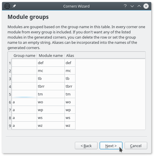
Specifying groups of modules for the corner generator. We specify only one group named “a” comprising modules wp, ws, wo, and wz.
In the next step we are going to define the parameter values that will be included in generated corners. The list is automatically filled with extreme values of operating parameters and zeros for statistical parameters. If multiple values are specified for the same parameter, every generated corner will use one of the specified values. The Alias column will be added to the names of generated corners. This way you can recognize which parameter values are associated with a particular corner by simply looking at its name.
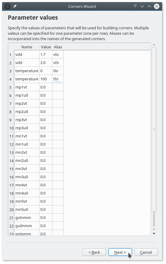
Specifying the parameter values for the corner generator.
We can specify a prefix for the names of generated corners. The corners can be numbered starting with an arbitrary value.

Specifying corner naming and numbering.
Before the corners are added to a task a list of names of all corners that will be generated is printed.
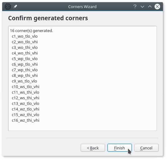
Previewing the list of corners.
After clicking “Finish” the corners are added to the task’s list of corners. We now have the initial “nominal” corner and 16 extreme corners.

Generated corners in the task’s list of corners.
The task is now ready to be run.