11.2.4. Analyses
Just like we added a simulator setup we can add analyses under the “Analyses”
tree item. We are going to explain in more detail how the operating point
analysis (named op) is set up. Analysis names must be unique identifiers.
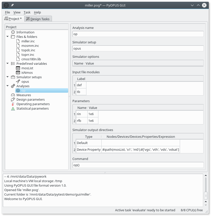
Setting up an operating point analysis.
The first thing you need to enter is the name of the simulator used by the analysis. The simulator setup determines the simulator and the input netlist modules that you can use in this analysis. Under Simulator options you can specify the simulator options passed via the netlist. Any values specified here override the values specified in the simulator setup. The same holds for the netlist parameters specified for a particular analysis.
The op analysis uses two input file modules: def and tb. The
first one defines the opamp subcircuit while the second one uses this
subcircuit definition in the top level circuit for adding subcircuit
instance x1 which represents the opamp. Note how we did not add the
MOS transistor models here. This is because we are going to add the models
when we will be defining the corners for the simulation of the circuit.
Typically device models are part of a corner definition because we want
to simulate the circuit’s performance for various extreme MOS models.
The Command entry is where you enter the function invoking the operating
point analysis (op()).
Finally, Simulator output directives specify what quantities the simulator should save in the output file. By default these are node potentials and certain branch currents (i.e. the ones that flow through voltage sources and inductors). If you want to save anything else you shuld specify it here.
We first specify the Default save directive which saves the above
mentioned voltages and currents. If we do not do this only the quantities
listed under save directives will be saved. The second save directive
specifies that the simulator should save the values of Vgs, Vth, Vds, and
Vdsat for all MOS transitors. This is done with the Device Property
save directive. For this directive one must specify a space-separated list
of instances and a space-separated list of quantities. You can use the
hash syntax for specifying these two lists. The expression can use the
variables defined under the Predefined variables node in the project tree.
The expressions are evaluated at simulation. In our example
ipath(mosList, 'x1', 'm0')
generates the list of simulator’s built-in MOS transistor instances corresponding to all MOS transistors in the circuits.
m0:xmn1:x1 m0:xmn2:x1 m0:xmn3:x1 m0:xmn4:x1 m0:xmn5:x1 m0:xmp1:x1 m0:xmp2:x1 m0:xmp3:x1
Similarly you can enter all other analyses. See Miller opamp design with PyOPUS for the details on other analyses.